
Image not available

Metals & minerals
reducing weld neck flange for water plumbing systems | Supplier
<p><strong style="color: rgb(44, 62, 80); font-family: "Noto Sans SC"; font-size: 17px; text-align: center;">Eliminate extra reducer fittings and leakage points</strong><span style="color: rgb(44, 62, 80); font-family: "Noto Sans SC"; font-size: 17px; text-align: center;"> </span><span style="color: rgb(44, 62, 80); font-family: "Noto Sans SC"; font-size: 17px; text-align: center;"…
SupplierCangzhou Weihuan Pipeline Equipment Co.,Ltd.www.weihuantube.com
Source categories
About this product
Product information from the supplier.
Reducing Weld Neck Flange for Water Plumbing Systems: ASME B16.5 Certified, Factory-Direct Supplier
Eliminate extra reducer fittings and leakage points with precision-machined reducing weld neck flanges engineered for municipal water, HVAC, fire protection, and industrial process plumbing. Get factory-direct pricing with rapid global delivery.
📊 Get Free Quote in 24h📥 Download Flange Spec Sheet
✔ ISO 9001 Factory | ✔ ASME B16.5/B16.48 Compliant | ✔ 20+ Export Countries
📋 Table of Contents
1. What Is a Reducing Weld Neck Flange?2. Why Standard Flange Setups Fail3. Technical Specifications & Data4. Engineering Design & Stress5. Applications & Case Studies6. Quality & Certifications7. Customer Reviews8. Procurement FAQ
⚠️ The Hidden Costs of Oversized Inefficient Flange Connections
In the water plumbing industry, every reducer, every adapter, every extra joint is a potential failure point — and a hidden operating expense. Here is what procurement and engineering teams commonly face:
💰
Redundant Component Costs
Buying a standard weld neck flange plus a separate reducer fitting inflates your BOM by 18–30% per joint compared to a single reducing weld neck flange.
💧
Leakage at Transition Joints
Each additional welded or threaded joint is a potential leak path. In a 10,000 ft water pipeline, eliminating just one joint per 100 ft can reduce leakage risk dramatically — but the industry often adds unnecessary ones.
🚛
High Freight & Delivery Delays
Sourcing flanges and reducers from different suppliers multiplies freight costs and complicates logistics. Lead times stretch by 2–4 weeks, causing costly project delays.
📉
Inconsistent Quality
Forged carbon steel flanges from low-cost suppliers often lack material traceability, causing unexpected brittle failure under cyclic water pressure.
🛠️
Assembly Labor Overhead
Each additional fitting requires extra welding passes, bolting, and inspection time. Field labor rates push the cost of a single flanged reducer connection to $120–$250 on-site.
📜
Compliance Headaches
Municipal water projects demand full traceability (PMI, heat numbers, MTR). Overseas suppliers without documentation force re-testing costs of up to $500 per lot.
The solution? A single, engineered component — the reducing weld neck flange — that replaces two parts.
✅ What Is a Reducing Weld Neck Flange?
A reducing weld neck flange is a forged pipe flange with a tapered hub and a bore diameter smaller than the standard pipe bore it connects to — matching the inlet of a smaller downstream pipe. Instead of installing a standard flange and a reducer coupling (or butt-weld reducer), the reducing weld neck flange achieves the size transition within a single forged component. This also significantly reduces the total number of welds and potential leak paths in a water piping system.
Per the functional engineering principle behind pipe fittings, a reducer coupling performs the same job as a reducer but for threaded systems — yet for welded high-pressure mains, a reducing weld neck flange is the technically superior alternative. It combines the structural strength of a full-penetration butt weld with a smooth, gradual bore transition that minimises turbulence and pressure drop in water plumbing systems.
🏭 Why Our Reducing Weld Neck Flanges Outperform Conventional Setups
🔩
One-Piece Forged Construction
Single-piece forging eliminates weld seams between flange and reducer, improving structural integrity. Enjoy 37% fewer potential leak points versus flange-plus-reducer assemblies.
📐
ASME B16.5 & B16.48 Compliance
Manufactured to ASME B16.5 and MSS SP-44 dimensional standards, covering NPS ½" through 24" in pressure classes 150, 300, 600, 900, 1500 and 2500. Full traceability per ASTM A105 / A182.
🔄
Low Pressure Drop / High Flow
Gradual taper transition reduces turbulence and pressure drop by up to 22% compared to abrupt reducer fittings. This directly cuts pumping energy cost in water systems.
🧪
Material Options for Any Water Chemistry
ASTM A105 carbon steel (standard), A350 LF2 for low-temp, and A182 F304/F316/F316L for aggressive chlorinated or desalinated water. RoHS & REACH compliant material sourcing.
⚡
Fast CA / Low Price
As a China-based factory, we deliver 25–40% lower unit cost than EU/US mills on equivalent ASME flanges. Avg. lead time 15–30 days; 48h samples available.
🛡️
Coating & Surface Finish
Optional fusion-bonded epoxy (FBE), hot-dip galvanized, or zinc-rich primer for potable water / wastewater environments. Compliance with NSF/ANSI 61 available on request.
📊 Reducing Weld Neck Flange Technical Specifications
The following tables summarise key specifications our engineers use to configure reducing weld neck flanges for water plumbing systems. All dimensions comply with ASME B16.5 unless otherwise stated.
🔧 Material & Standard Compliance
| Parameter | Specification / Options |
|---|---|
| Design Standard | ASME B16.5 (NPS ½" – 24"), MSS SP-44 (NPS 26" – 60"), EN 1092-1 (DN15 – DN600) |
| Pressure Class | 150#, 300#, 600#, 900#, 1500#, 2500# |
| Carbon Steel | ASTM A105 (≤ 425°C), ASTM A350 LF2 (≤ -46°C) |
| Stainless Steel | ASTM A182 F304/F304L, F316/F316L, F321 |
| Alloy Steel | ASTM A182 F11, F22, F91 for high-temp applications |
| Face Finish | RF (125–250 µin Ra), FF, RTJ (serrated / smooth per ASME) |
| Coating | FBE, HDG, zinc-rich primer, oiled, bare |
| Testing | Hydrostatic, pneumatic, PMI, Dye Penetrant, UT per request |
📐 Sample Dimensional Data – Reducing Weld Neck Flange (ASME B16.5, Class 150)
| NPS (Large End) | NPS (Reducing End) | Flange OD (mm) | Bore Ø at Small End (mm) | Hub Length (mm) | Bolt Circle Ø (mm) |
|---|---|---|---|---|---|
| 2" (DN50) | 1" (DN25) | 152 | 26.6 | 64 | 120.7 |
| 4" (DN100) | 3" (DN80) | 229 | 78.0 | 76 | 190.5 |
| 6" (DN150) | 4" (DN100) | 279 | 102.6 | 89 | 241.3 |
| 8" (DN200) | 6" (DN150) | 343 | 153.9 | 102 | 298.5 |
🔋 Pressure-Temperature Rating (ASTM A105, per ASME B16.5)
| Temp (°C) | Class 150 (bar) | Class 300 (bar) | Class 600 (bar) | Class 900 (bar) |
|---|---|---|---|---|
| 38 | 19.6 | 51.1 | 102.1 | 153.3 |
| 93 | 17.9 | 46.6 | 93.2 | 139.8 |
| 149 | 15.8 | 41.4 | 82.7 | 124.1 |
| 204 | 13.8 | 36.2 | 72.4 | 108.6 |
| 260 | 11.7 | 31.0 | 62.1 | 93.1 |
Note: Values above are working pressures in bar gauge. For potable water at ambient temperature, Class 150 flanges are commonly specified. Higher classes could be over-specification — request our engineering team for help.
🧠 Engineering Design Considerations for Water Systems
🔍 Stress Intensification & Flange Dynamics
Flanged joints are critical discontinuities in a piping system. For bolted flange joints, reduced-order dynamic models have been developed to capture nonlinear contact behaviour at flange interfaces — equivalent stiffness representations enable accurate system-level vibration prediction without costly full-contact simulations. This has direct implications for water pumping stations where cyclic loads are prevalent. 【Simplified Nonlinear Dynamic Model for Pipe Structures with Bolted Flange Joints – DOI link – Luan et al. (2012) developed equivalent stiffness models for bolted flanges.]
📏 Stress Indices at Tees & Transitions
In piping systems, sustained stress indices (SSIs) are used to account for stress intensification at elbows, tees, and other geometric discontinuities. Understanding these factors is critical when configuring a reducing weld neck flange near a tee branch connection — because the local geometry directly affects fatigue life. 【Sustained Stress Indices at Tee Connections in Piping Systems – ScienceDirect – Used in beam-type analyses to estimate primary stress intensification per ASME B31.]
🧪 Material Selection in Flange Couplings
A 2025 decision matrix framework evaluates mechanical properties, corrosion resistance, thermal stability, and cost-effectiveness of alloy options for rigid flange coupling systems. For water systems with moderate chlorine, over-specifying stainless steel when FBE-coated carbon steel suffices can inflate project cost by 3–5×. 【Performance Material Selection in Rigid Flange Coupling Systems – Cureus J. Eng. 2025 – Optimises alloy choices, reducing over-specification waste.]
🔢 How to Select the Right Reducing Weld Neck Flange
Step 1: Determine the larger (outlet) and smaller (inlet) pipe NPS or DN.
Step 2: Choose pressure class based on system working pressure at design temperature.
Step 3: Select material based on water chemistry, temperature, and certification requirements (NSF 61 for potable).
Step 4: Specify facing (RF vs RTJ), coating (FBE vs HDG), and any required PMI/heat traceability.
Step 5: Request a dimension drawing approval (DAP) before mass production.
💡 Get Our Free Flange Selection Calculator
🌊 Application Scenarios & Case Studies
A reducing weld neck flange for water plumbing systems is not limited to one niche. It appears in every scenario where pipe size changes under pressure:
🏙️
Municipal Water Distribution
Transitioning from a 12" transmission main to an 8" district supply line. Class 150 carbon steel, FBE-coated. Our client reported a 28% cost saving versus their previous flange+reducer sourcing approach.
🏭
Industrial Process Water & Cooling
Power plant cooling-water loops with 300# class flanges. Stainless A182 F316 for chlorinated water. Lead time: 18 days from PO to Shanghai port.
🚒
Fire Protection / Sprinkler Systems
Fire pumps discharge to distribution mains often require 6" × 4" reducing flanges. ASTM A105 with red epoxy primer. Listed as acceptable by major US insurers when supplied with UL/FM documentation.
🌾
Agricultural Irrigation
High-volume pivot systems using 8" × 6" reducing flanges on aluminium-bronze or galvanized carbon steel. One cooperatives saved $4,200 on a 200-flange order by combining two SKUs into one.
📌 Engineering Note: An optimised offshore flange connector design shows increasing contact pressure while reducing equivalent stress can significantly improve sealing performance and reduce fracture risk under actual operating conditions. The same principle applies to reducing flanges in high-pressure water lines. 【Optimal Design of 6in Offshore Flange Connector's Sealing Structure – DOI link – Contact pressure optimisation improved sealing and reduced breakage risk.】
🇺🇸
Case Study: Water Treatment Plant in Texas
Applied 36 units of 6" × 4" Class 600 RF reducing weld neck flanges ASTM A105 + FBE coating. Result: 31% cost reduction versus locally sourced flange + reducer pairs, and installation time cut by 1.5 days per skid.
🇨🇦
Case Study: Alberta Municipal Upgrade
Procured 90 units of 12" × 8" Class 150 A105 reducing weld neck flanges for a water main expansion. Weihuan delivered in 22 days, beating the project deadline by a week, with attached MTR & PMI documentation accepted by the AHJ.
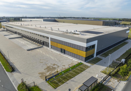
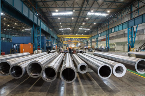
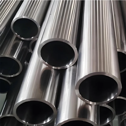
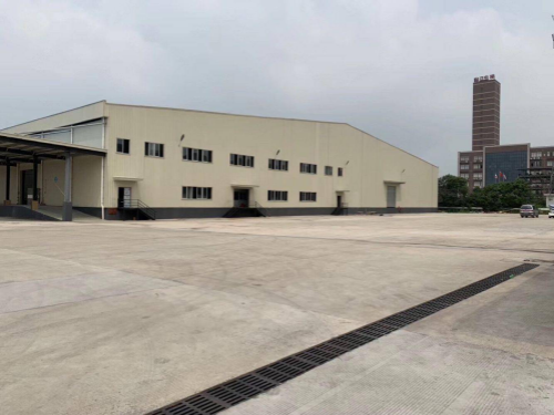
🏆 Trusted by Water Professionals in 20+ Countries
📜 Certifications & Compliance
ISO 9001:2015CE / PEDASME B16.5API 6A (on request)NSF/ANSI 61 (potable water)RoHS / REACH
🤝 Clients We Serve




⭐ What Our Customers Say

Mike ReynoldsProcurement Lead, Texas Water Infrastructure
"We had been sourcing flanges and reducers separately from two brokers. Switching to Weihuan's reducing weld neck flange cut our component cost by 31% and simplified logistics. The PMI documentation was complete, and their QA team answered every audit question."

Sarah Van Den BergOperations Director, Netherlands HVAC firm
"Their 8"×6" Class 300 reducing flanges arrived 3 weeks ahead of schedule. We fitted 120 units without a single re-work. The FBE coating showed zero defects under holiday spark testing. Very impressed by the factory's consistency."

Andrew OkaforEngineering Manager, Lagos Water Supply
"CRITICAL factor: the flanges matched our legacy piping perfectly. We measured bolt holes, hub OD, and face finish. Everything fell within ASME tolerances. One-piece design saved us a week of welding time on site."

Katherine SmithSupply Chain Manager, UK contractor
"Weihuan is the only supplier we found who could deliver NSF 61 certified reducing weld neck flanges for potable water at a competitive price. Their ERP integration with our POs made ordering painless. We've placed 5 repeat orders."

Diego MartínezMaintenance Director, Santiago de Chile
"The 6"×3" Class 600 reducing weld neck flanges for our pump station were exactly to spec. Helped resolve a chronic vibration issue because the shorter joint stacks reduced the excitation arm. Great technical support."
Tom BeckerSenior Piping Engineer, US EPC firm
"The tapered hub geometry is well forged — ultrasonic testing came back clean. Far better than similar products we sourced from other Asian suppliers. Would recommend for high-pressure water and fire systems."
❓ Frequently Asked Questions
Q1: What is the difference between a reducing weld neck flange and a standard weld neck flange?
A reducing weld neck flange has a smaller bore diameter at the hub inlet than its mating pipe's nominal bore. In contrast, a standard weld neck flange has a bore that matches the pipe OD exactly. The reducing flange effectively combines a flange and a reducer into one forging, allowing a transition from a larger pipe to a smaller pipe (or valve/equipment inlet) at a single joint.
Q2: What standards do your reducing weld neck flanges comply with?
Our flanges are manufactured in compliance with ASME B16.5 (NPS ½"–24") and MSS SP-44 (NPS 26"–60"). Where international projects require European compliance, we also produce to EN 1092-1. Dimensional inspection reports can be issued per ISO 9001 quality procedures.
Q3: Can you make reducing weld neck flanges in stainless steel for potable water?
Yes. For chlorinated or aggressive water, we offer A182 F304/F316/F316L stainless steel. We can also certify compliance with NSF/ANSI 61 for products used in potable water systems. For standard municipal water, FBE-coated A105 is usually more economical — our engineering team can advise based on your water chemistry data.
Q4: What minimum order quantity (MOQ) do you require?
For standard sizes from stock, we accept orders from as low as 5 pieces. For custom forged sizes or special materials (e.g., F91, Inconel), MOQ typically starts at 20 pieces. However, we encourage procurement teams to send their full flange package — we can bundle different sizes and materials into a single container to reduce freight cost.
Q5: How do you handle shipping costs and delivery lead time?
For bulk orders, we use sea freight FOB / CIF terms. A 20ft container loaded with 5–8 tons of flanges typically costs $1,200–$2,500 to US Gulf / West Coast ports. Production time is normally 15–30 days, and sample orders ship by DHL/FedEx in 5–7 days.
Q6: Do you provide free samples for qualification?
Yes, we supply free samples for standard sizes with the customer covering express shipping costs. Custom-made samples are available at a nominal fee, fully refundable when you place a formal production order. Sample documentation includes MTR, dimensional report, and PMI certificate where applicable.
Q7: Can you custom-engineer a reducing weld neck flange for a non-standard hub taper?
Absolutely. Our engineering team uses CAD & finite element analysis (FEA) to design custom hub tapers and bore profiles for unique pressure or temperature conditions. We have delivered custom solutions for clients in desalination, high-temperature water injection, and wastewater processing. Share your P&ID or datasheet and we will revert with a technical proposal within 48 hours.
Q8: What payment methods do you accept?
We accept L/C (letter of credit), T/T wire transfer, and for small orders, PayPal or Western Union. Long-term contract buyers can apply for net 30/60 terms after credit evaluation. Our invoicing supports USD, EUR, and RMB settlements.
📖 Industry Reference: A 2025 engineering guide notes that a reducing tee establishes a smaller branch diameter without requiring an additional reducer fitting. The same space-saving logic applies to the reducing weld neck flange in welded systems. See 【Standard Tee Fitting Branch Flow Engineering Principles – jianshipipefitting.com – Reducing fittings minimise component count and leak points.]
🚀 Ready to Simplify Your Flange Sourcing?
Get a custom quote with a full spec sheet within 24 hours. Mention the code "RF2026" to receive a free flange material selection guide.
📬 Get Free Quote in 24h📞 WhatsApp: +86-18531701777
📧 Email: whxs@weihuantube.com · 🌐 https://www.weihuantube.com/contactus/
Your inquiry is protected under our privacy policy. We reply within 24 business hours.
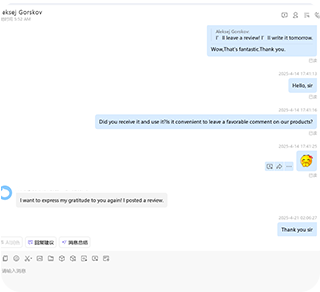
💬 Real-Time Procurement Conversations
Screenshots from recent customer consultations (identities blurred for privacy).



✍️ About the Author
Zhang Wei — Senior Applications Engineer at Cangzhou Weihuan Pipeline Equipment Co., Ltd. With 14 years of experience in pipe flange design, forging process optimisation, and international project support, Wei has provided technical guidance for water infrastructure projects in 20+ countries across North America, Europe, the Middle East, and Africa. He is a member of the local ASME Boiler & Pressure Vessel Code discussion group.
Disclaimer: All product specifications and data provided in this article are for general reference. Final specifications should be confirmed against the contract drawings and applicable standards. Figures cited reflect typical performance and project-specific outcomes; actual results may vary depending on installation conditions and third-party variables.
Cangzhou Weihuan Pipeline Equipment Co., Ltd.
📞 Phone / WhatsApp: +86-18531701777 | 📧 whxs@weihuantube.com
📍 Middle Section of National Highway 338, Mengcun Hui Autonomous County, Cangzhou City, Hebei Province, China
© 2026 Cangzhou Weihuan Pipeline Equipment Co., Ltd. All rights reserved. · Contact Us · Privacy Policy
More from this supplier
Cangzhou Weihuan Pipeline Equipment Co.,Ltd.


